Showing posts with label engine. Show all posts

Entomology A bee!

All last summer there were no bees, and I had to polinate everything by hand.

The closest thing to a bee in the last year Ive seen, was a dead one at my mums house 10 minutes drive away from my house.

No bees.

They are all dying out everywhere on the planet.

Colony collapse disorder I think its called.

But I saw one, alive and kicking in my backyard today.

After chasing it around for half an hour as it frantically tried to escape my shade cloth I finally got a pic of it.

Thanks rapid fire camera maker.

Tis a poor pic, but it does prove a bee still lives.


120 Things in 20 years - Entomology - Yay BEE!
Read More..

Fire Quicker more durable ethanol stove

A while back I made a pretty convincing ethanol camp stove out of a coke can.

It worked well and looked like this when it was running.

Ive used it a bit since then and its definitely a practical addition to any backpack.

The problem is its starting to show signs of aging. The can expands and contracts, and there is now a crease where extra gas flows giving an uneven flame.


In my model (also not my design) I used an inner sleeve with holes at the top to let the gas out. The result is that the trapped ethanol (spirit/alcohol/methanol) between the outside wall, and the inner wall boils the spirit, and creates a gas jet that looks a lot like a normal BBQ burner.

One of the problems was trying to get the top of a coke can to fit into the bottom of a coke can. Its tricky because (of course) they are the same size. It can be done, but involves gently stretching the outside one and it takes a lot of messing about.

Now Im being pretty fussy here. The little burner works really well, but it did tend to leak fuel around creases that formed in the join between the top and the bottom sections.

Someone on a Stirling engine forum pointed me towards a different method of making one. This method involves no holes, but it just encourages those creases that mine developed by itself, and I think it might be a winner.

Theirs also used a drink can, but I think it might make a more robust version if I used a tinned food can.

So, to start with, I peeled a normal, every day food tin.


The first step was to trim it to size.

I needed the top to fit into the bottom, so the first thing to do was punch a hole in it to enable a cutting tool to get in there.

I used that mystery tool that pocket knives have.

Probably a leather working tool or something.

Who knows, just punch a hole in the can.


Next jam in some tin snips or something to make a nice cut to separate top from bottom.

My tin snips are stupid, so I ended up using scissors.

This isnt the best way to use scissors, so dont do this at home unless you actually own the scissors.


One very good method of cutting a tin can, is to just tear it by grabbing a ragged tail of tin with a pair of pliers and twist. If theres a groove to follow, it actually makes a pretty straight cut.


As I said, I ended up using scissors to trip everything to it was nice and neat.

I made the inside sleeve (the one on the left), slightly taller than the other so the pot could sit on the rim and let the gas escape from the gap between the outside sleeve.


I bent a series of grooves in the base of the inner sleeve so that they would allow the flow of gas, and also allow the inside sleeve to fit inside the outside sleeve.

This was simply a case of grasping with pliers, and twisting them to the left, and slightly down toward the centre.


Next I inverted the inside sleeve and carefully positioned the outside sleeve over it so that I might press the two together by stamping down with my foot.


Which failed completely.
Read More..

Stirling engine ver 2

I made a few changes to My little home made Stirling Engine.

Change is always required when your engine seizes after only 55 seconds.

This one ran until the plastic bits caught fire.

Much better...


The original displacer popped itself to bits when it got hot enough, so this new version has a different design thats open to air travelling through it.

The autopsy also shows why my little engine stopped so suddenly. There is only around a quarter of an inch of air above and below the displacer when its at its extremities, and the bottom popping off made the displacer touch the bottom of the can it was in.


I replaced the can surrounding the displacer because I had to use a can opener to get the displacer out, and reattached the power piston balloon.

In the process of building the new displacer can, I discovered a new way to drill a hole that suits my personality perfectly.

You punch a hole with a nail, then rip a circular hole with pointy nose pliers in much the same way as opening an old style tin can of fish that the eater would open with a key.


If you arent old enough to know what Im talking about it, count yourself lucky and get on with it. You havent missed a thing.

I drilled a few large holes in the top and bottom of the displacer, and packed it full of stainless steel, kitchen scrubber pad.

Apparently this works, and acts as a thing called a regenerator.

A regenerator can often be found on a Stirling engine and acts to store heat between the hot and cold sections as the air moves between the two.


The regenerator material collects heat from the freshly heated air inside the can the displacer is in. As the heat is displaced from the hot section to the cold section, some heat is removed and stored in the material. This is a good thing, because we want the cold side of the equation to be as cooled as possible. When the cooled air returns to the hot end, it picks up the heat it dropped into the regenerator on the way through, making it heat up more rapidly.

Its not by magic that the heat knows when to sit and when to be picked up, just that the air is hotter on the way up from the heated section, and has cooled a bit at the top before coming back through the regenerator.

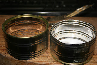
I put the new displacer in its tin can, and threaded its wire through the bottom of the top can that holds the crank shaft.


In the process of de-constructing the first version, I bent the shaft a little, and it never ran quite as smoothly again. The little Stirling engine took a lot more heat to get it going this time, but Im not sure if it was due to the new design of the displacer, or just due to the fact that every thing was a bit warped.

Friction really kills these things, so making sure the shaft is straight is a must.

It does run, and its going a lot faster than the first version, but I suspect that has to do with all the extra heat from using a gas burner rather than a candle, and not some gain in efficiency.

I think I now know a little more about these interesting engines, and a little more about the universe in general, and I think Ill have another go at building a better one. Id really like to make one efficient enough to run on the waste heat from my wireless router so it could just jig around all day for free.


120 Things in 20 years is finding the universe yet more interesting as a result of building this version 2 of my first, working, home made Stirling engine.
Read More..

Stirling Engines My first Stirling engine build

In spite of my video camera running out of battery during filming, I managed to get the first (and only) moments of my first Stirling engine running.

Tis a funny kind of beast running so slowly and deliberately.

I officially like Stirling engines. Mine looked like this...


It ran for a total of about a minute before the displacer fell to bits. It was sealed airtight, and as it got hot it just popped. It turns out there isnt really any need to make it air tight.

I think.

My displacer started life as a soft drink can.

I marked out a straight line to cut it down to size.

I took a guess as to what size it should be.

I scratched a series of arcs with a bent piece of sharp wire, each at different points, to find the centre, then punctured it with a drawing pin. 

I marked out another can, but this time much shorter.


Then squashed the big one over the little one after turning the little one upside down.
This gave me a sealed can again.

I glued it with super glue.

The gluing was what killed my brand new Stirling  engine after only 60 seconds. As the heat increased, so did the pressure inside the sealed displacer, and eventually it popped open.


I poked a straight length of fencing wire through both holes, then bent and super glued one end to stop it slipping through.


My wire originally had a slight loop at the other end, but I had to cut it off to remake the thing after I glued myself to it.

Dont do that.

And if you want to be really scared, use super glue, then adjust the dials and buttons on your new camera with the same fingers.

Anyway, the main thing is stick some wire through the displacer.

Next I took a tin can and smacked a hole in it with my familys trusty meat mallet.

This meat mallet used to be my mothers (it probably still is), and was used as the household hammer for as long as I can remember.


Here we see the entire family history of hammering.

Actually thats half the family history of hammering. The other half is of course, on the other side.


So then, I took the length of wire sticking out of the displacer (soft drink can thing), and threaded it through the bottom of the tin can.


Like this.

Its a bit difficult to see, but thats the soft drink can displacer thinggy under the tin can.


Next, I took another tin can and drilled a big hole in the side.


And sanded down a small plastic bottle so that its contour matched the tin cans.


Then cut a really big hole in the side of the small plastic bottle.

Something like a pill bottle would work.
All this, so I could glue the small plastic bottle on the side of the tin can with a big hole in the side. 


Next, I stretched a balloon over the entire little plastic bottle, and pulled the slack so that it was tight everywhere but the top.

I also glued a length of wire to the centre of the slack bit.

This, believe it or not, is something called a "power piston".

Ill explain what all this stuff does later.


Next I bent a crank shaft, and some mounting points for the wires coming from the displacer (through the bottom of the tin can), and the wire glued to the balloon (power piston)

The crankshaft has one offset bit (offset by around 8mm) to attach the displacers wire, and another to attach the power piston wire to.

The two offset, (bent out) bits, are at 90 degrees to each other.

So from the left...

straight, then down, then straight, then back up to the original.

That makes the first cranky bit.

Then continuing straight, then back, then straight, then forward back to the original plane.

That makes the next cranky bit.

If you look at the crankshaft end on, if one crank was at 12 oclock, the other would be at 3 oclock (or 9)

I found this almost impossible to get on camera (or to explain), but it looks like this.

Its probably best seen on the video.

The crankshaft is lightly held in place with two inverted U shaped bits of wire taped to the sides. (just visible near the top, left rim of the device)


I stuck a cardboard disk about the size of a CD onto the end of the shaft to act as a flywheel, and then added nuts and bolts with blu-tac until the thing was balanced.

To get them in the right spot, I put the disk in a random place, and if it rolled back to a different position, Id stick on a weight so it wouldnt.

I should have been able to do this with just one weight of the correct size, but for some reason it was beyond me.

So...

  • The displacer is the soft drink can thing inside the bottom can. 
  • The bottom can is sealed ([buy - EDIT  - note from the future-  Who makes errors like this?] by the top tin can) except for the small hole in its top that has the displacers wire poking through.
  • The displacer travels up and down inside the bottom tin can with a total travel of around 1cm.
  • The displacer gets very close to the top and bottom of its tin can container, but never actually touches.
  • The displacers wire is connected to the crankshaft (between pink beads)
  • The power piston (pink balloon) is floopy, and connects to the crankshaft 90 degrees offset from the displacers crank.
  • The top tin can is there to hold up all the other kit, and as the top seal for the chamber holding the displacer (soft drink can thing)
  • When the air inside the bottom tin can heats up it expands, forcing the power piston up. This turns the crank and gives the device its power.
  • As the device rotates, and the displacer moves down, forcing the air up and away from the heat, so it cools and contracts. 
  • When it contracts, the power piston is sucked down.
Thats pretty much it. Repeat as desired, or until something breaks. 

Some light oil can be added to any surfaces that have friction. (where the displacer wire moves up and down into the bottom tin is a high friction area)


==============>>> IMPORTANT!!! Note from the future - It turns out you probably shouldnt add oil to the point where the wire slides through the can. Theres a chance of explosion as the oil is heated to a gas. <<<================


120 things in 20 years - I made a Stirling engine!


Read More..

Stirling engine Success!


I just made an engine!

I even think I got it on video.

It ran for about a minute at around 78 rpm before making a popping sound and seizing up.

Which would have been perfect if it was connected to an old record player...

playing a very short song...

that I only wanted to hear once.

The camera battery went flat during filming, but but the video should be on there. Ill find out tomorrow. If not, Ill just fix it.

Yay me!

More later...


120 Things in 20 years is very pleased with itself       :{)
Read More..

Photography Improvised macro lens mould study

I got another lens from a junk bin in a camera store.

This one is a canon f 1.4, 35-80mm zoom.

It has an auto focus motor that makes a sound a bit like you might hear if you put a blender in a blender, but the auto focus still works.

The bits that dont work so well, are the lenses.


The problem is mould inside the lens.

Not uprising for a 500 Yen lens sitting in the junk bin of a camera store in the country that invented humidity.


Thats a ridiculously close up shot of the mould.

Ridiculously close up.


I dont have any way of doing macro shots with my new camera, so I had to improvise.

I took the shot of the mould with this home made bit of kit.

The blue lens cloth is there to keep the light out of the improvised macro lens, because the small length of toilet roll acting as an extension tube  isnt light tight.

The lens attached (thats a generous description) to the camera is actually on backwards, and is resting against the other end of the toilet roll tube.

The lens resting on the red kitchen scrubber is the new one with the mould garden inside.


The torch is a torch.

The torch is there because the cameras lens has the aperture set as small as it will go (f36) to try to get at least some of the mould in focus.

I didnt really achieve that.

The exposures were around 30 seconds long (many minutes without the torch), and other people were working in the house at the time. My desk is a wobbly kitchen table top heavy with old CRT computer monitors, and all the other junk I like to keep at hand. As as a result it amplifies any movement from people, traffic, and the fridge and freezer compressors.

If you put a glass of water on a desk like mine and look at the reflection, you will see the reflected image dance all over the place. Normally it isnt a problem, because the camera and lens would both move at the same time, but with this contraption, there was nothing of substance connecting the lens and the camera.

Tricky.

Anyway...

The lens has mould in it.

The image on the left was taken with the canon 18-55mm lens that came with the camera.

The image on the right is taken with the mouldy 35-80mm lens.

The camera was set to the same settings for both shots.


Mould is not a friend of the lens.

The point of all this, is to point out that I wont be taking an angle grinder to my lens in some future post  without reason.

Actually Ill try to open it up and clean it, but there is a fair chance its bits of glass are coated in a very delicate plastic coating, called coating. If thats the case the mould may have become a permanent fixture by etching its way into the coated bits.

The mould appears to be on only one element, so I might be able to salvage some other bits and make a proper, mould-free macro lens.


120 Things in 20 years warns that when I say "proper" I mean the improvised macro lens might employ slightly fewer toilet paper tubes, and where they are unavoidable, they might be made a bit less wobbly and light leaky.
Read More..

Stirling engine Slow motion power piston video

Opps.

For some reason the video wasnt displayed on my last post.

Here is the video for those that missed it...


Read More..

Thinking Paradise

Paradise is usually documented by pristine beaches that have an opalescent, turquoise quality.

Its just polarised light.

Buy some polarised sunglasses and look at your local beach.

Wear them all the time, and theres no need to fly anywhere!

This tip brought to you in the interest of staying at home. Its got everything you need!

Except broad horizons.

No matter where you are, the horizons are not broad enough.

Travel if you can.
Read More..

Stirling engines Adjustable Stirling engine crankshaft

Ive been busy making the tips of my fingers raw.

Wire seems to enjoy hurting people.

But I love the stuff.

My time learning how to make screw in eyelets for my hand made fishing lures was well spent. Every new skill I pick up seems to inform my next project. Working with wire is a really worthwhile thing to learn.


  • This post appears to be in bullet point style.


One thing I dont really understand is the relationship between the size of the cams on the crankshaft and the performance of my little tin can Stirling engines. With this lack in mind, I thought Id build a completely adjustable crank shaft.

It looks like this.

With it, it should be easy to try a stack of different configurations to see what they do.

The cams (bits that are offset from the main shaft) should offer different combinations of engine torque, and speed when they are adjusted to different heights.


I think.

Ideally I need an adjustable chamber for the displacer as well. Ill have to feed that idea through the invention engine at some stage because I have no idea on that one.

All the brass fittings come from the brass bits in strip electrical connectors.

Once the screws are undone as far as they can go, all the brass bits fall out with tap and a jiggle.

Lots of taps and jiggles actually, but they all come out in the end.


In my adjustable cam, the brass tubes that accommodate the cams have had an extra hole drilled through. Brass is very easy to drill, and a pleasure to work with. I dont think Ive ever done anything with brass before.

I officially like brass.


  • Bullet points


Also, many other people have used these as the adjustable bits on Stirling engines, and my only contribution to the science is to take their use to absurd levels.


120 Things in 20 years - No time to post because Im too busy learning stuff about Stirling engines.


All the brass bits are taken from a strip of electrical connectors.


Read More..

Stirling engines My first Stirling engine

Sometimes I struggle a bit with certain aspects of construction, but in this case I wasnt even certain of what I was attempting to construct.

Most of the problems trend around a certain frantic waste of pace and failure to pay attention to detail.

This time was no different.

A Stirling engines basic list of components include a cylinder, a displacer, and a crankshaft.

They also include a hot bit, and a cold bit.

Its the difference between the hot bit and the cold bit that makes a Stirling engine an engine.


Theres also another really important bit, called the power piston. The power piston is connected to the same crank shaft, but on another crank. This crank is offset from the displacers crank by 90 degrees.

Im not really sure how it does what it does, but this is my first attempt at making a Stirling engine.

The power piston is the bit thats missing, because I didnt get that far.


Some of the other missing bits include the rest of the components that make up a Stirling engine.


120 Things in 20 years - On a scale of one to ten, where one is a total fail, and ten is a total success, I wouldnt bother rating my first attempt at making a Stirling engine.
Read More..